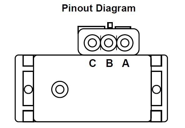
Gm Iat Sensor Wiring Diagram
Vt Commodore Ignition Wiring Diagram, Complete Wiring Diagrams For Holden Commodore VT, VX, VY, VZ, VE, VF, 5.36 MB, 03:54, 32,796, John Amahle, 2018-08-01T19:37:41.000000Z, 19, Vt Commodore Ignition Wiring Diagram, to-ja-to-ty-to-my-to-nasz-swiat.blogspot.com, 1272 x 1800, jpeg, bcm pcm 12j swiat nasz, 20, vt-commodore-ignition-wiring-diagram, Anime Arts
One part is the intake air temperature (iat) sensor and the other is the manifold absolute pressure (map). Iat sensor wiring diagram intake air temperature (iat) sensor wiring diagram the intake air temperature sensor of the car is a thermistor. The maf sensor is connected underneath inside the duct. A thermistor is an electrical resistor that changes its resistance value with the.
Apr 14, 2015 • 2006 toyota tacoma. Chevy monte carlo iat. Good afternoon, i need the location and wiring diagrams for the iat sensor on a 2015 chevrolet silverado 2500 crew cab 6. 0l gas please. Ask your own chevy question. Where is the iat sensor located on. There aer 5 wires on : Chevy cruze maf iat sensor wiring diagram. Wire map and iat sensor for mss54hp csl ecu diy • buildjournal. Iat sensor wires those chips are not chips just a 5 cent resistor to alter the iat (intake air temperature) signal to the pcm (powertrain control module), the idea is that the engine control computer thinks it is getting colder air than it really is and slightly increases spark advance, u will feel no difference in power but u may gain 1 mpg in fuel economy, so u decide.
| Repair Guides | Electronic Engine Controls | Manifold Air Temperature (mat)/intake Air
What two wires do i hook the chip to on the iat sensor on 2005 gmc canyon

Which specific wires are the IAT sensor wires on a 2012 Camaro 3.6L? What position on the MAF

Iat Sensor Wiring Diagram Gmc 2008 - Wiring Diagram

Wiring your GM Map Sensor / IAT Sensor for use with a 'CSL' clone ECU - ECUWorx

P0113 Honda Crv 2005 - Mansoor ahmad auto electrician efi&ac workshop. - Lainey Love
Repair Guides
wiring gm/aem map & gm/aem iat sensors - ClubLexus - Lexus Forum Discussion

I am installing a performance chip on my 2005 GMC Sierra 2500HD 6.0L which requires a connection

I have a 2011 Yukon Denali. I don't have the wiring diagram but I need to identify the two wires
