Heat And Cool Thermostat Wiring Diagram

Vt Commodore Ignition Wiring Diagram, Complete Wiring Diagrams For Holden Commodore VT, VX, VY, VZ, VE, VF, 5.36 MB, 03:54, 32,796, John Amahle, 2018-08-01T19:37:41.000000Z, 19, Vt Commodore Ignition Wiring Diagram, to-ja-to-ty-to-my-to-nasz-swiat.blogspot.com, 1272 x 1800, jpeg, bcm pcm 12j swiat nasz, 20, vt-commodore-ignition-wiring-diagram, Anime Arts
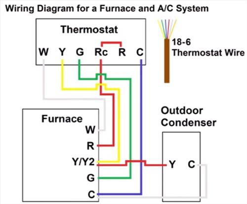
For a heating + cooling application there will be a heat load wire and a cool load wire (see illustration above left) one of which will be fed by the thermostat depending on whether it is in heating or cooling mode. In this hvac installation training video, i show how to wire the low voltage thermostat wires into a furnace and ac unit. I explain what each of the letter t. This diagram is to be used as reference for the low voltage control wiring of your heating and ac system.
18 gauge single stage heat thermostat variable speed air handler standard condenser ac contactor ** * y2 y1 o note (see below) 24 volt+ Tim smith from hudson valley community college discusses specific concepts found on a two stage heating and cooling wiring diagram. Tim uses the interactive. Power for heating, 24v. Rc* power for cooling, 24v. C** common wire, 24v. Indoor blower (fan) y. First stage outdoor cooling on conventional systems or first stage outdoor heat and cool on heat pump systems. Y2/* second stage outdoor cooling on conventional systems or second stage outdoor heat and cool.
Collection Of Heating and Cooling thermostat Wiring Diagram Download

Electric Heat Thermostat Wiring Diagram - Line Voltage Thermostats For Heating Cooling - If it

Heating And Cooling Thermostat Wiring Diagram | Thermostat wiring, Hvac thermostat, Hvac

Heating And Cooling Thermostat Wiring Diagram - Collection - Wiring Diagram Sample

Thermostat heat and cool 2 transformers | Thermostat wiring, Refrigeration and air conditioning

Collection Of Heating and Cooling thermostat Wiring Diagram Download

Heating and Cooling thermostat Wiring Diagram | Free Wiring Diagram

Wiring Diagram For Thermostat - Wiring Diagram Schemas

Collection Of Heating and Cooling thermostat Wiring Diagram Download

Radiant Cooling | Twinsprings Research Institute
