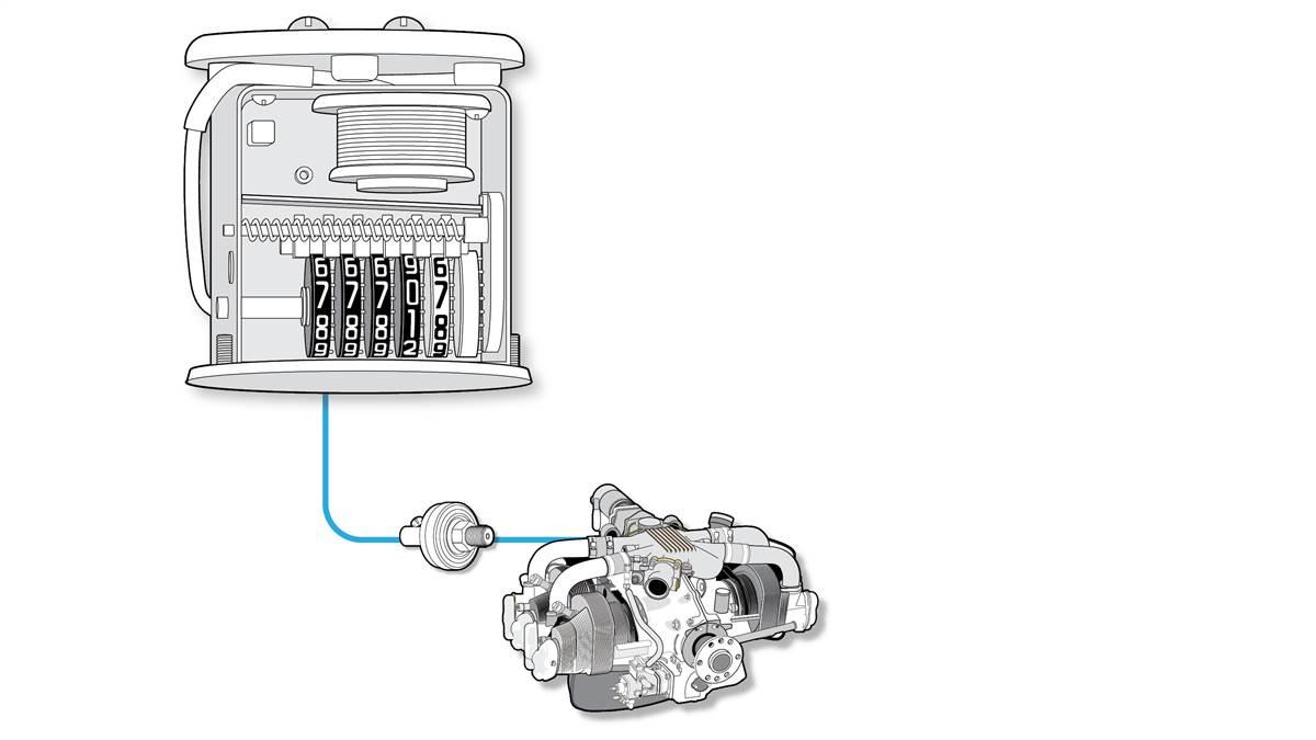
Hobbs Hour Meter Wiring Diagram

Vt Commodore Ignition Wiring Diagram, Complete Wiring Diagrams For Holden Commodore VT, VX, VY, VZ, VE, VF, 5.36 MB, 03:54, 32,796, John Amahle, 2018-08-01T19:37:41.000000Z, 19, Vt Commodore Ignition Wiring Diagram, to-ja-to-ty-to-my-to-nasz-swiat.blogspot.com, 1272 x 1800, jpeg, bcm pcm 12j swiat nasz, 20, vt-commodore-ignition-wiring-diagram, Anime Arts
Chase the wires out the back of the meter to see where they go. If things are documented properly, the poh would be updated with weights and updated wiring diagrams. If you replaced an existing hobbs then there probably is a pressure switch on the oil line. Unfortunately, i don't have much knowledge of where to look on your engine for that.
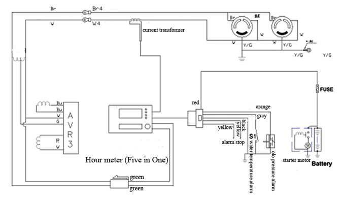
Hobbs meter wiring diagram. I would thing that these wires need to come from the motor so the meter will only run when the switch is on. 20000 series wiring diagrams 120vac meter applications mount part 20174 20183 20116 20182 20171 20170 20177 n n single phase 2 wire. I was getting ready to wire the hobbs meter and pressure switch, but could not find instructions. As always, van's to the rescue. They sent a pdf diagram, but basically it amounts to: The meter is not polarity sensitive. One terminal of the meter is wired to the no terminal of the switch. The c terminal of the switch goes to ground.
Hobbs Hour Meter 12v Wiring Diagram - Wiring Diagram and Schematic

Hobbs Hour Meter Wiring Diagram
Hobbs Hour Meter Wiring Diagram
Hobbs Hour Meter Wiring Diagram
Hobbs Hour Meter Wiring Diagram
Hobbs Hour Meter Wiring Diagram

Hobbs Hour Meter Wiring Diagram - Terrian Info

Hobbs Hour Meter Wiring Diagram - 20

Hobbs Hour Meter Wiring Diagram - 20

Engine Hour Meter Wiring Diagram - Wiring Diagram
